Homework5
Due Date: 10/26/01
Comparison of Requirements Specification Methods:
Structured Analysis and Design Technique (SADT)
and Unified Modeling Language (UML)
Structured Analysis and Design Technique (SADT)
Background material
SADT is a technique developed by Douglas T. Ross in 1974 that is useful for system planning, requirements analysis and system design. It was developed to provide a rigorous, disciplined approach to achieve understanding of user needs prior to providing a design solution. SADT did not evolve from a design technique, but rather was developed by examining the problems associated with defining systems requirements. It is generally not used for software module (program) design since the constructs necessary for program design of sequence, selection and interaction are not found within SADT. The recommended approach is to employ SADT in the planning, analysis and general design phases and use other techniques (Constantine, Jackson, Warnier/Orr, Pseudo, etc.) for detail design activities.
The purpose of SADT is to organise, display and provide a straightforward technique for identifying and cross referencing all information necessary for publication of acceptable requirements and design specifications. SADT is a tool to structure information and allows the engineers a better understanding of the problem that is to be solved. Therefore SADT is mainly used for mindsetting and structuring the analysis and design phases. SADT doesn't supply a complete specification.
Representation of components,
relationships and rules
An SADT model is an understanding; a simple representation of some reality which is adequate for a given purpose. To achieve the benefits of the principles of structuring, especially top-down, levels of detail and hierarchy the model should be graphic. Each SADT model consist of a set of related diagrams (Figure 1) which are organized in a top-down manner. Each diagram is either a summary (parent) diagram or a detailing (child) diagram of the parent.
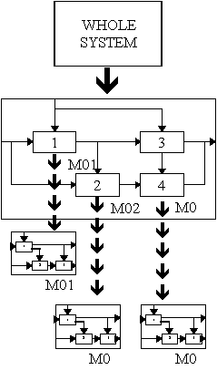
Figure 1: Parent and child diagrams.
Chronological numbers or "C-Numbers" are used to identify unique versions of a diagram, and they are also used to link together diagrams in the model hierarchy. The C-Number of the diagram that decomposes a box is placed underneath that box on the parent diagram. Then the parent diagram is referenced on the child diagram.
During the development of an SADT model, a diagram with its boxes and arrows is usually redrawn several times, creating different versions of the diagram. SADT uses a diagram configuration control scheme, built upon chronological numbers or "C-numbers", to distinguish different versions of the same diagram from each other. A C-number code is constructed from the author's initials and unique sequence number. These codes are put in the lower right-hand corner of the SADT form. Those C-numbers are also used to identify unique versions of a diagram, they are also used to link together diagrams both downwards and upwards in the model hierarchy.
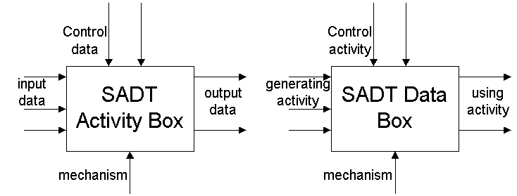
SADT makes use of two types of models, namely activity models and data models. A SADT activity model describes the decomposition of activities. A SADT data model describes the decomposition of data. On the left side of the box is the input data, or (in case of the data model) activity that generates data. At the right side of the box is the output data or the activity that uses the data from the box. On top of the box is the control data or activity. SADT makes a distinction between input and control data. The input of the diagram is actually transformed. The control data is only used for guiding the activity.
These are the two simple representations of the two types of models:
Strengths of SADT
- Precise and consise scheme to represent graphically complex system
requirements.
- The notation is easy to understand, and the requirements can be
discussed at whatever level is appropriate for the customer.
- Clear top-down decomposition for I/O and control.
- Avoids cluttering by segregating data from activities.
- Distinguishes between control data from mere input data.
Weaknesses of SADT
- When there are a lot of diagrams arranged in a hierarchical order,
it can become difficult to understand due to the additional control
information on the diagrams.
Appropriate Domains of
Application
- Large or complex process oriented systems.
- Environments requiring mulltiple designers.
- Useful in depicting activities in a software development process.
- Military mobilzation plan. SADT is also known in the U.S. Department
of Defense as IDEF0.
Inappropriate Domains of
Application
Example
The diagram shown in Figure 2 describes the functions associated with obtaining personnel for a large automobile manufacturer. The diagram describes both automated and manual activities and establishes the requirements for an application tracking system. Seen in a larger context, this diagram could be one function in a total personnel system.

Figure 2: A sample SADT Activity diagram.
Related tools and
methodologies
The SADT methodology emcompasses automated tools to support analysis procedures and a well-defined organizational harness through which the tools
are applied. Reviews and milestones are specified, allowing validation of
developer-customer communication.
Automatic control engineering ORCHIS is a graphical and interactieve environment designed for the IDEF0 method implementation. It is a set of graphical and textual editors integrated to the windowing system. Acces to command is done by pull down and pop up menus.
The development of an application is done through 3 stages:
- Specifying the system with automatic control of the syntax in the graphic editor. You formalize the behaviour of your hierarchical system with activity boxes connected to one another by arrows. Also you have a label editor, a definition editor and the text editor.
- Check the consistency of the modelized system according to the Idef-0 standard. A checker scans the selected Idef-0 object, indicates the inconsistencies, and show errors met.
- Writing the documentation. It compose a review document where you can define the cover page, chose in the summary the activity boxes to be pinted, and select printing of the graphic and/or textual parts.
Unified Modeling Language (UML)
Background material
The Unified Modeling Language (UML) is a language for specifying, visualizing, constructing, and documenting the artifacts of software systems, as well as for business modeling and other non-software systems. The UML represents a collection of best engineering practices that have proven successful in the modeling of large and complex systems.
The development of UML began in late 1994 when Grady Booch and Jim Rumbaugh of Rational Software Corporation began their work on unifying the Booch and OMT (Object Modeling Technique) methods. In the Fall of 1995, Ivar Jacobson and his Objectory company joined Rational and this unification effort, merging in the OOSE (Object-Oriented Software Engineering) method.
The efforts of Booch, Rumbaugh, and Jacobson resulted in the release of the UML 0.9 and 0.91 documents in June and October of 1996. During 1996, the UML authors invited and received feedback from the general community. They incorporated this feedback, but it was clear that additional focused attention was still required.
During 1996, it became clear that several organizations saw UML as strategic to their business. A Request for Proposal (RFP) issued by the Object Management Group (OMG) provided the catalyst for these organizations to join forces around producing a joint RFP response. Rational established the UML Partners consortium with several organizations willing to dedicate resources to work toward a strong UML 1.0 definition. Those contributing most to the UML 1.0 definition included: Digital Equipment Corp., HP, i-Logix, IntelliCorp, IBM, ICON Computing, MCI Systemhouse, Microsoft, Oracle, Rational Software, TI, and Unisys. This collaboration produced UML 1.0, a modeling language that was well defined, expressive, powerful, and generally applicable. This was submitted to the OMG in January 1997 as an initial RFP response.
In January 1997 IBM, ObjecTime, Platinum Technology, Ptech, Taskon, Reich Technologies and Softeam also submitted separate RFP responses to the OMG. These companies joined the UML partners to contribute their ideas, and together the partners produced the revised UML 1.1 response. The focus of the UML 1.1 release was to improve the clarity of the UML 1.0 semantics and to incorporate contributions from the new partners. It was submitted to the OMG for their consideration and adopted in the fall of 1997.
Representation of components,
relationships and rules
The OMG specification states:
"The Unified Modeling Language (UML) is a graphical language for visualizing,
specifying, constructing, and documenting the artifacts of a software-intensive system.
The UML offers a standard way to write a system's blueprints, including conceptual
things such as business processes and system functions as well as concrete things such
as programming language statements, database schemas, and reusable software
components."
The important point to note here is that UML is a 'language' for specifying and not a method or procedure. The UML is used to define a software system; to detail the artifacts in the system, to document and construct - it is the language that the blueprint is written in. The UML may be used in a variety of ways to support a software development methodology (such as the Rational Unified Process) - but in itself it does not specify that methodology or process. UML defines the notation and semantics for many domains. For requirements specification domain, UML has the the following:
- The User Interaction or Use Case Model - describes the boundary and interaction between the system and users. Corresponds in some respects to a requirements model.
The UML also defines extension mechanisms for extending the UML to meet specialised needs (for example Business Process Modeling extensions)
Use Case Model
The Use Case Model describes the proposed functionality of the new system. A Use Case represents a discrete unit of interaction between a user (human or machine) and the system. A Use Case is a single unit of meaningful work; for example login to system, register with system and create order are all Use Cases. Each Use Case has a description which describes the functionality that will be built in the proposed system. A Use Case may 'include' another Use Case's functionality or 'extend' another Use Case with its own behaviour. Use Cases are typically related to 'actors'. An actor is a human or machine entity that interacts with the system to perform meaningful work.
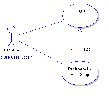
A Use Case description will generally include:
- General comments and notes describing the use case.
- Requirements - Things that the use case must allow the user to do, such as , & etc.
- Constraints- Rules about what can and can't be done. Includes i) pre-conditions that must be true before the use case is run - e.g. must precede ; ii) post-conditions that must be true once the use case is run e.g. ; iii) invariants: these are always true - e.g. an order must always have a customer number.
- Scenarios - Sequential descriptions of the steps taken to carry out the use case. May include multiple scenarios, to cater for exceptional circumstances and alternate processing paths.
- Scenarios - Sequential descriptions of the steps taken to carry out the use case. May include multiple scenarios, to cater for exceptional circumstances and alternate processing paths.
- Additional attributes such as implementation phase, version number, complexity rating, stereotype and status
Actors
Use Cases are typically related to 'actors'. An Actor is a user of the system. This includes both human users and other computer systems. An Actor uses a Use Case to perform some piece of work which is of value to the business. The set of Use Cases an actor has access to defines their overall role in the system and the scope of their action.

Constraints, Requirements and Scenarios
The formal specification of a Use Case includes:
- Requirements. These are the formal functional requirements that a Use Case must provide to the end user. They correspond to the functional specifications found in structured methodologies. A requirement is a contract that the Use Case will perform some action or provide some value to the system.
- Constraints. These are the formal rules and limitations that a Use Case operates under, and includes pre- post- and invariant conditions. A pre-condition specifies what must have already occurred or be in place before the Use Case may start. A post-condition documents what will be true once the Use Case is complete. An invariant specifies what will be true throughout the time the Use Case operates.
- Scenarios. Scenarios are formal descriptions of the flow of events that occurs during a Use Case instance. These are usually described in text and correspond to a textual representation of the Sequence Diagram.
Sequence Diagrams
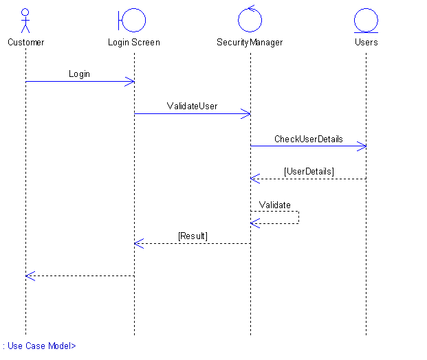
UML provides a graphical means of depicting object interactions over time in Sequence Diagrams. These typically show a user or actor, and the objects and components they interact with in the execution of a use case. One sequence diagram typically represents a single Use Case 'scenario' or flow of events.
Sequence diagrams are an excellent way to document usage scenarios and to both capture required objects early in analysis and to verify object usage later in design. Sequence diagrams show the flow of messages from one object to another, and as such correspond to the methods and events supported by a class/object.
The diagram illustrated below shows an example of a sequence diagram, with the user or actor on the left initiating a flow of events and messages that correspond to the Use Case scenario. The messages that pass between objects will become class operations in the final model.
Implementation Diagram
A Use Case is a formal description of functionality the system will have when constructed. An implementation diagram is typically associated with a Use Case to document what design elements (eg. components and classes) will implement the Use Case functionality in the new system. This provides a high level of traceability for the system designer, the customer and the team that will actually build the system. The list of Use Cases that a component or class is linked to documents the minimum functionality that must be implemented by the component.
Strengths of UML
- Provides users with a ready-to-use, expressive visual modeling language so they can develop and exchange meaningful models.
- Provides extensibility and specialization mechanisms to extend the core concepts.
- Is independent of particular programming languages and development processes.
- Provides a formal basis for understanding the modeling language.
- Encourages the growth of the OO tools market.
- Supports higher-level development concepts such as collaborations, frameworks, patterns and components.
- Integrates best practices.
Weaknesses of UML
- UML is really rich and this richness is its strength but also its most important danger. Without a properly documented method above UML, developers and non experts in methodology, will use inadequate concepts at inadequate moments. They could be lost in the numerous diagrams and descriptions that UML offers.
- New specification which means it is not widely accepted as being valid
- Not well suited for small projects
Appropriate Domains of
Application
- Used for larger systems
- Used in domains where requirements are not very well-defined at the very beginning
- Used in development of long-term software applications which may include
maintenance
Inappropriate Domains of
Application
- Should not be used in small software projects since there may be too much overhead and time consumed in following the whole process
- Should not be used for short-term software
Example
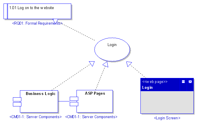
The example below shows that the Use Case "Login" implements the formal requirement "1.01 Log on to the website". It also states that the Business Logic component and ASP Pages component implement some or all of the Login functionality. A further refinement is to show the Login screen (a web page) as implementing the Login interface. These implementation or realisation links define the traceability from the formal requirements, through Use Cases on to Components and Screens.
Related tools and
methodologies
The Rational Unified Process is a software engineering process that provides a disciplined approach to assigning and managing tasks and responsibilities within a development organization. RUP uses the UML visual notation and provides guidelines on how to how to use the UML effectively. RUP has been developed hand-in-hand with the UML.
Rational Software provides the following tools for requirements and analysis:
- Rational Suite AnalystStudio
- Rational RequisitePro
- Rational Rose
References
- Sommerville, Ian. Software Engineering, Addison Wesley.
- Schach, R. (1999), Software Engineering, Fourth Edition, McGraw-Hill, Boston, MA.
- Leffingwell, Dean et.al., Managing Software Requirements A Unified Approach, Addison Wesley.
- Schneider, Geri et.al., Applying Use Cases A Practical Guide, Addison Wesley.


