Project7
Due Date: 11/30/01
Detailed Design for Equipment Tracking System
OO/UML Design
The OO (object oriented) method was used to design our project with reference to the following:
- Functional and operational requirements of the system
- Clear and unambiguous description of how the user and the system interact
- Basis for validity and testing
The OO analysis method enables us to model a problem by representing static and dynamic characteristics of classes and their relationship as the primary modeling components.
We have followed the UML notation for detailed design of the equipment tracking system (ETS). The UML notation offers a diagrammatic representation of the system. UML allows us express an analysis model using modeling notation that is governed by a set of syntax, semantic and pragmatic rules.
UML focuses on the user model and structural model view, which we incorporated into our system design.
UML offers various diagrams to document design activity. We have chosen the activity diagram, the class diagram and the sequence diagram for the ETS.
Activity Diagram
The activity diagram shows the interactions of the different components in the system. There are the Web pages which serve as the client. The web-pages are served by the Web Server. The web pages are not HTML pages but special pages which are capable of running code of a high-level programming language like Java/C++. Examples of these pages are ASP (Application Server Pages) or JSP (Java Server Pages). These web pages serve dynamic content. They make service calls to the ETS server which services these requests. The web pages run on the application server which compiles them into HTML pages and sends them to the Web Server to be sent to the client.
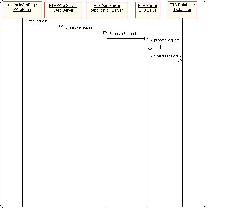
Figure1 : Activity Diagram for the Equipment Tracking System
Class Diagram
This diagram describes the types of objects in the system and various kinds of static relationships which exist between them. There are three principal kinds of relationships which are important: associations (a customer may rent a number of videos), subtypes (a nurse is a kind of person) and aggregation (an engine is part of an aircraft).
The class diagram details the various objects in the ETS server and their inter-relationships. These objects are the core of the ETS server and together they service requests made to the ETS server. These objects also interface to the database to store, retrieve and update data.
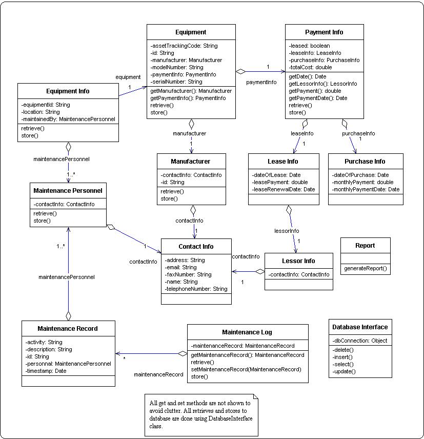
Figure2 : Class Diagram for the Equipment Tracking System
Sequence Diagram
Interaction diagrams are models that describe how a group of objects collaborate in some behavior - typically a single use-case. The diagrams show a number of example objects and the messages that are passed between these objects.
The sequence diagram below describes how an equipment object is stored into the database. The requirement here is that all information relevant to an equipment be stored into the database. There can be several sequence diagrams for different scenarios.
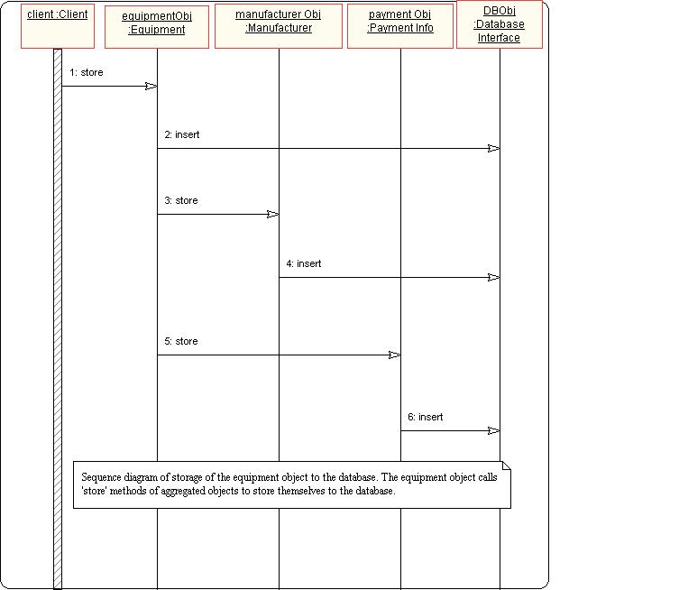
Figure3 : Sequence Diagram for storage of equipment information into the database
There could be several other UML diagrams done in the design phase. Examples of these are collaboration diagrams, state diagrams, package diagrams and deployment diagrams. The use of these diagrams depend from project to project. In this project, we have shown all relevant diagrams for the ETS.
